knowledge-base
Architecture Style: Space-Based
Description
This architectural style comes from the notion that in traditional web faced applications, the database is the ultimate bottleneck which is expensive and complex. When a load of traffic comes in, one would first scale the web servers, afterwards the application servers and last the database servers. So we just move the scaling issue from the front tier to the database tier. For many systems this might not be a real concern, however high-volume applications with large concurrent user load will ultimately run into the database limitations.
Space-Based is specifically designed to address these problems involving high scalability, elasticity, and high concurrency issues. Also useful for applications that have variable, unpredictable concurrent user volume. Solving the extreme and variable scalability issue architecturally is often a better approach than trying to scale out a database or retrofit caching technologies into a nonscalable architecture.
Topology
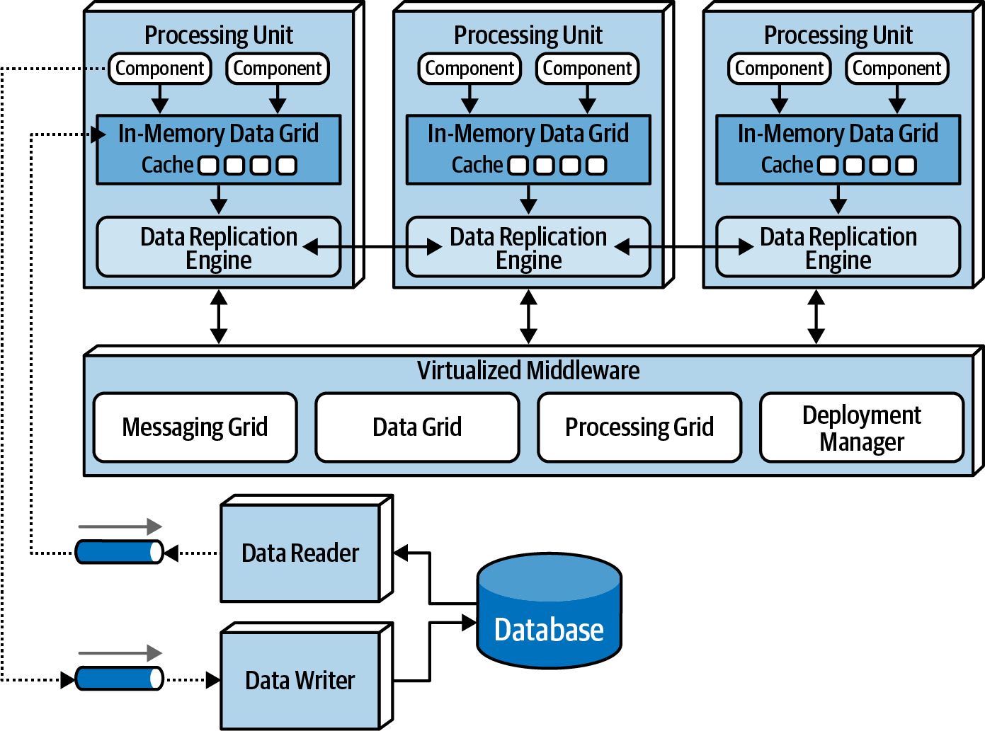
Name is based on the concept of tuple space, the technique of using multiple parallel processors communicating through shared memory.High scalability, high elasticity, and high performance are achieved by removing the central database as a synchronous constrain in the system and instead leveraging replicated in-memory data grids. Applications data is kept in-memory and replicated among all the active *processing units**. When a processing unit updates data, it asynchronously sends that data to the database, usually via messaging with persistent queues. Processing units start up and shut down dynamically as user load increased and decreases, thereby addressing variable scalability. Because there is no central database involved in the standard transactional processing of the application, the database bottleneck is removed, thus providing near-infinite scalability within the application.
There are 5 core architecture components:
- Processing Unit: Containing the application code
- Virtualized Middleware: To manage and coordinate the processing units
- Data Pumps: To asynchronously send updated data to the database
- Data Writers: To perform the updates from the data pumps
- Data Readers: To read database data and deliver it to the processing units upon startup.
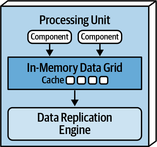
1. Processing Unit (PU)
Contains (entire or portions) of the application logic (including web based components and backend logic). Small webapps might be in a single PU, larger may split functionality in multiple PU based on functional areas. A PU could also be a single-purpose service (e.g. Microservice). If PUs have different logic, then we talk about different PU types. PUs can communicate between each other.
In addition it contains in in-memory data grid and replication engine usually implemented through products like Hazelcast, Apache Ignite or Oracle Coherene.
2. Virtualized Middleware
Handles the infrastructure/operational concerns within the architecture. These components can be self written or COTS.
2.1 Messaging Grid: Manages input request and session state. When a request is received, the messaging grid will decide to which PU the request should be forwarded. This can be round-robin or more complex algorithms, usually implemented using a typical web server with load balancing (e.g. Nginx, HA Proxy). 2.2 Data Grid: Perhaps most crucial and important component. This is the controller for the data grids found in the PU and their synchronization. Based on the data grid, it might be that no “central controller” is required, but usually it is. The idea is that data is replicated in all PUs. All PUs are aware of each other, and when a (named) cache is updated, that update is propagated immediately across all other PUs. Ensuring all named caches to be in sync. 2.3 Processing Grid [optional]: Responsible for orchestrated request processing, for when a requests needs multiple PU types for processing a request (e.g. Order Processing Unit and Payment Processing Unit). 2.4 Deployment Manager: Responsible to shut down or start up new UP based on load. This is your auto-scaling logic.
)
)
)
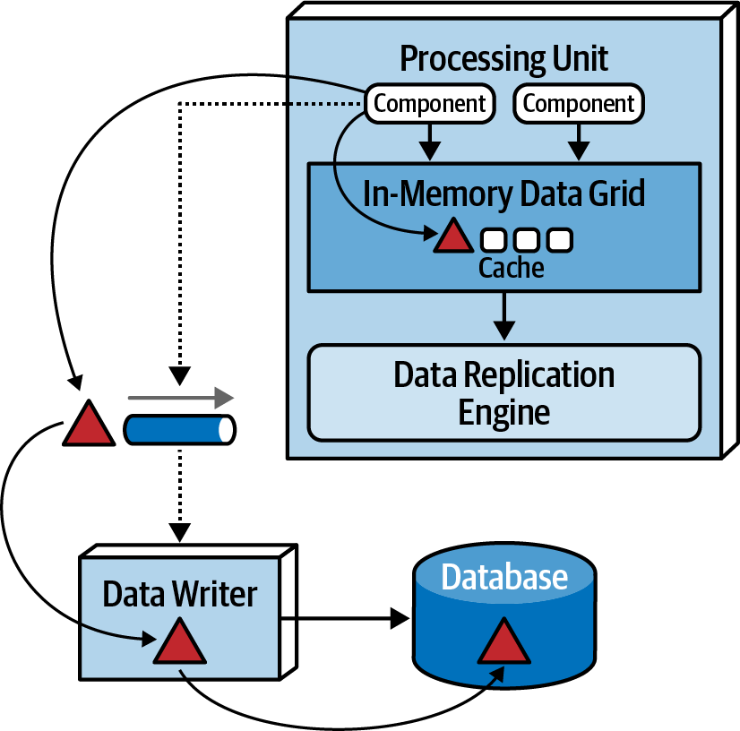
3. Data Pumps
A processing unit updates its cache, the cache then needs to propagate this to shared cache, and then this change must be propagated to the database. SO this change is send to a data pump. Processing units don’t read/write from/to the database. These pumps are usually implemented using messaging. Multiple pumps might exist, dedicated to certain (Sub)-domains or other scope/modelling logic. Pumps usually have associated contracts.
4. Data Writers
Diagram: General Data Writer Diagram: Dedicated Data Writers
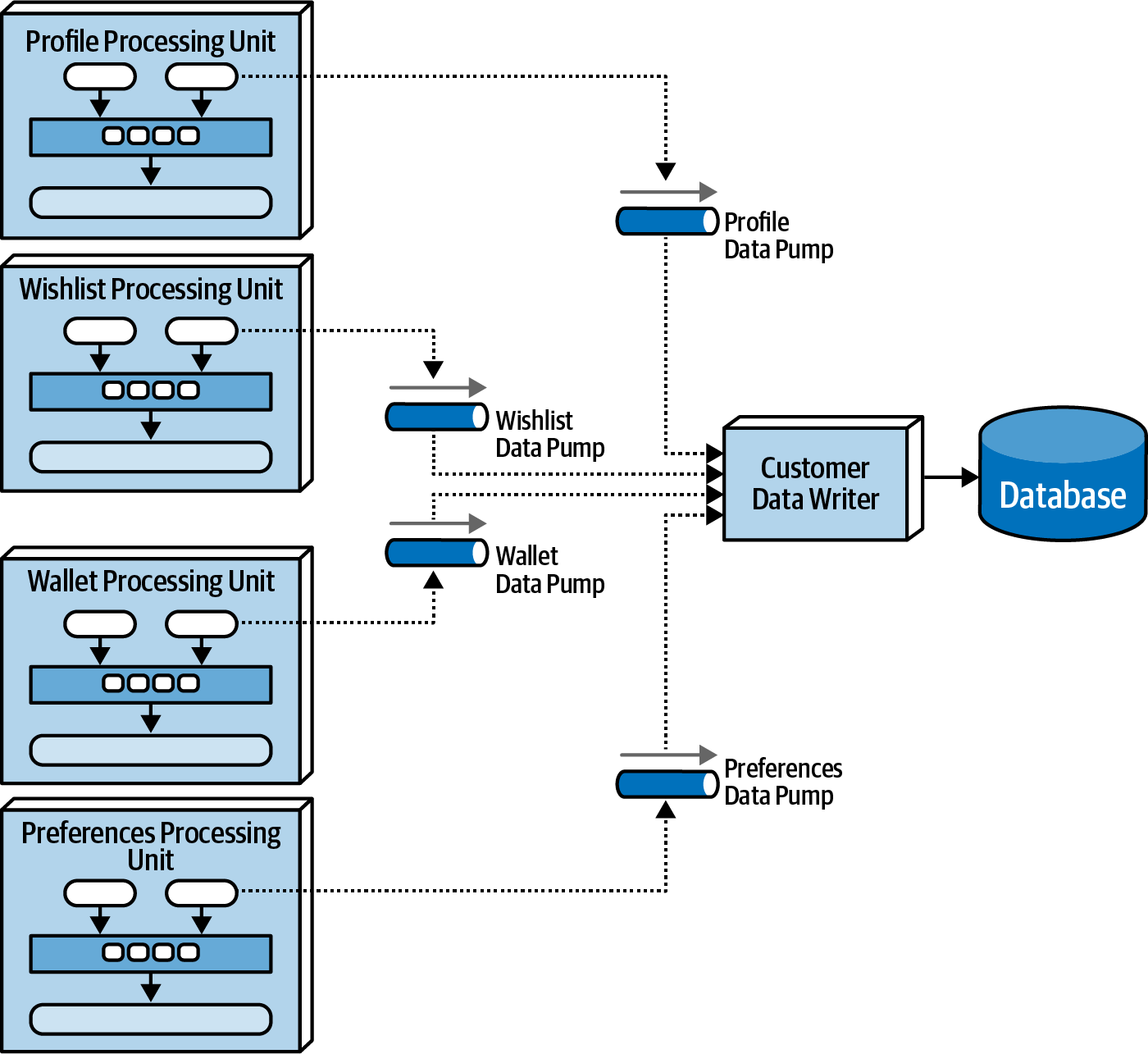
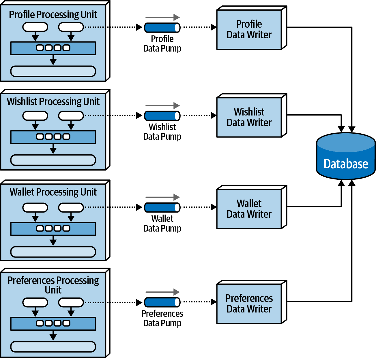
Accepts the updates from the data pumps and processes them in the database. The granularity of the data writers depend on the scope of the data pumps and processing units. A single data write can also accept from multiple data pumps that all have their own scope.
5. Data Readers
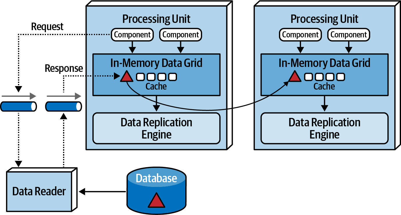
Send reading data from database to processing units via reverse data pump. Data readers are invoked under following situations:
- A crash of all processing units instances of the same named cache
- A redeployment of all processing units within the same named cache
- Retrieving archive data not contained in the replicated cache.
Just like data writers and pumps, these can be scoped on arbitrary domains.
Data Collisions
See * Fundamentals of Software Architecture: Chapter 15 for detailed calculations and the variables that impact that.
Cloud vs On-Premise Implementations
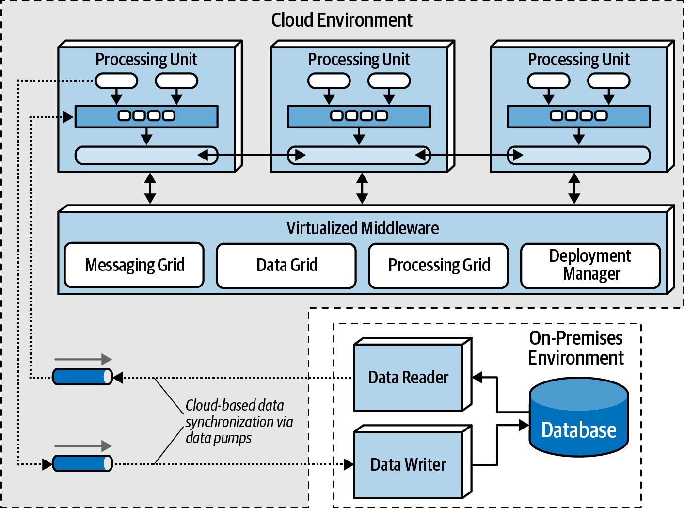
Unique to this architecture, one can place the database on-prem and all the other PUs and Virtualized middleware on the cloud for scalability. This can assist in regulatory and security concerns.
Replicated vs Distributed Caching
Space-based architecture mostly depends on replicated caching, although distributed caching can be used as well. Both can be also used based on the PU types. Consider leveraging based on the domain/functionality what caching strategy works best, See the optimization row in the table below.
| Decision Criteria | Replicated Cache | Distributed Cache |
|---|---|---|
| Optimization | Performance | Consistency |
| Cache Size | Small (<100 MB) | Large (>500MB) |
| Type of data | Relatively static | Highly dynamic |
| Update Frequency | Relatively low | High update rate |
| Fault Tolerance | High | Low |
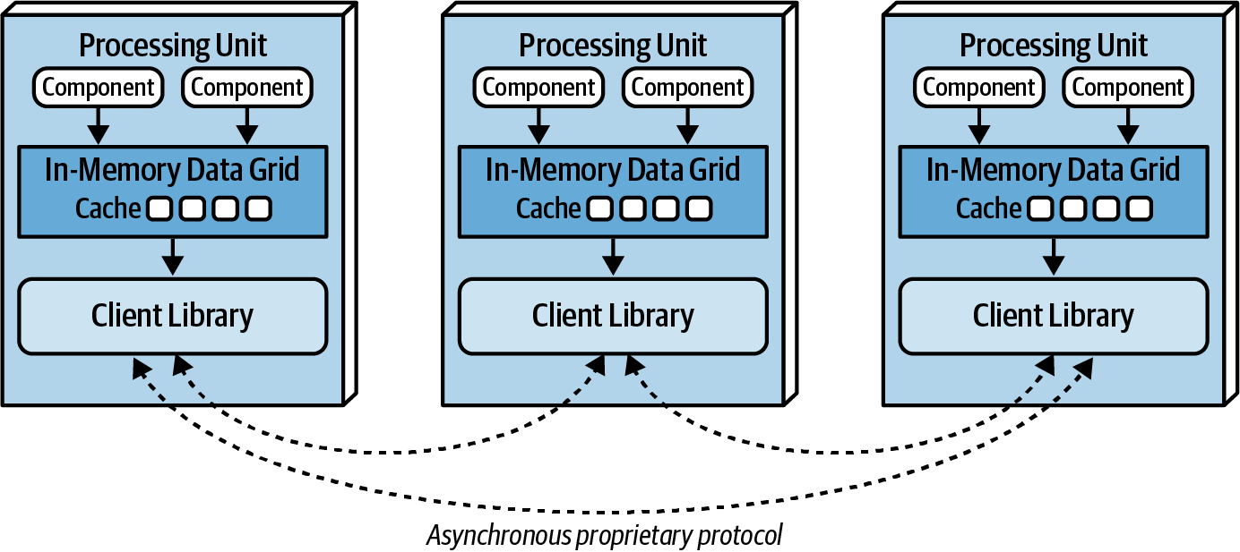
Replicated Caching
Each PU contains its own in-memory data grid that is synchronized between all processing units using the same named cache. When an update happens to that named cache in any of the PUs, other PUs are automatically updated with that information. THis is not extremely fast, but has high level of fault tolerance as there is no single point of failure.
This is the default model, however, in some situations, distributed cache is more desireable.
Distributed Caching
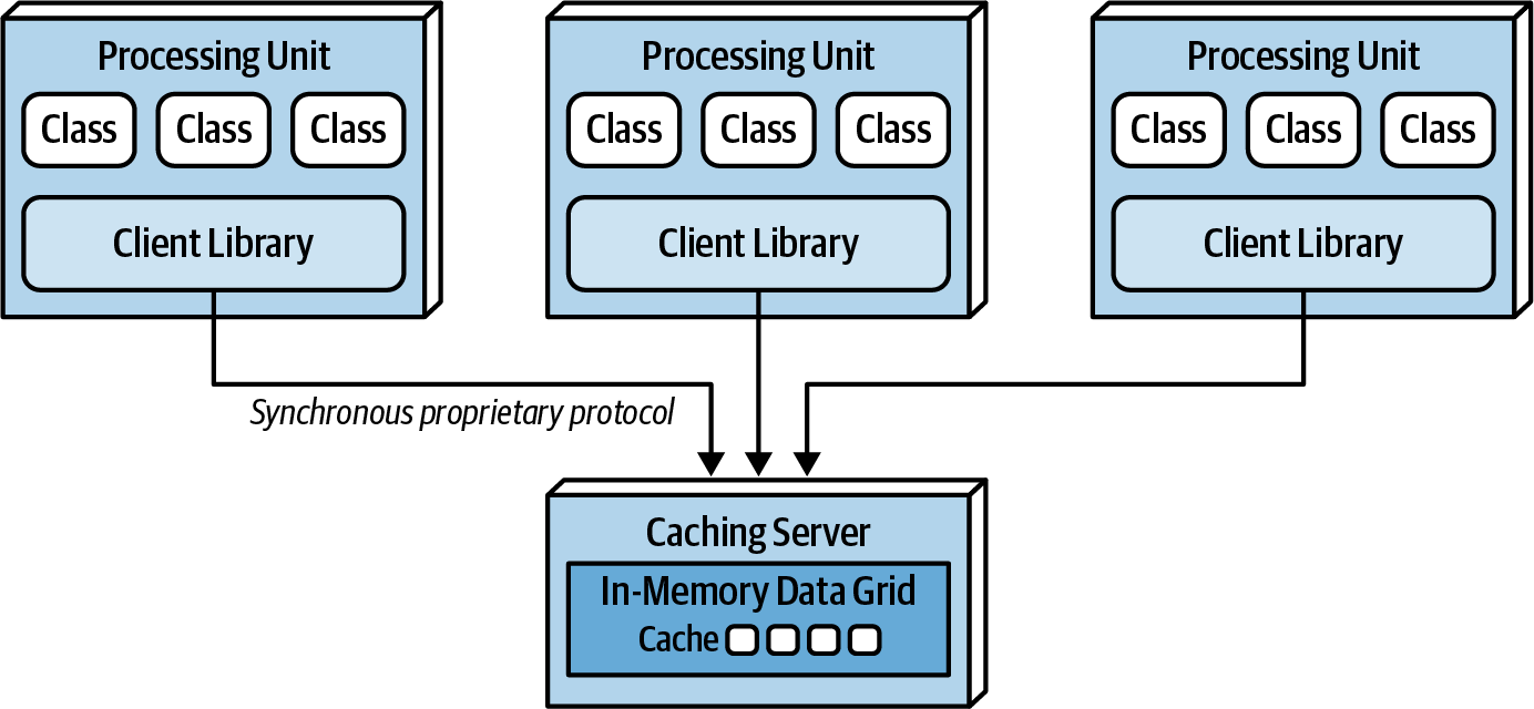
This is used when there is high data volumes (size of cache) and high update rates to the cache data. Internal memory caches in excess of 100 MB might start to cause issues as the amount of memory used buy each PU becomes high. When these (RAM) memory issues occur, update rate of the cache data is too high, the data grid might be unable to keep up. In these situations you need distributed cache most likely.
This requires an external server or service for the central cache server which is distributed underneath. Since the cache is not co-located in the PU, there might be a lower access speed.
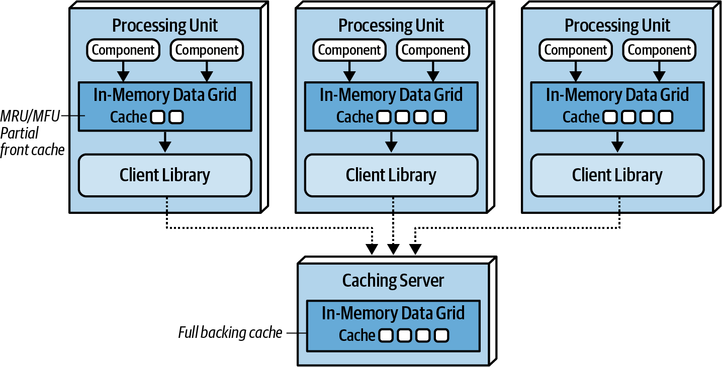
Near-Cache Considerations
Near-cache is a type of hybrid model bridging in-memory data grids with a distributed cache.
- The distributed cache is referred to as Full backing Cache.
- Each in-memory data grid contained within each PU is referred to as the front cache.
- The front cache contains smaller subsets of the full backing cache, using an eviction policy.
- MRU: Most Recent Used
- MFU: Most Frequent Used
- RR: Random Replacement
- The front cache contains smaller subsets of the full backing cache, using an eviction policy.
PUs don’t synchronize data not between each other! Goes all via the Caching server. This creates inconsistencies in performance and responsiveness between PUs because each PU contains different data in the front cache. For this reason near-cache model is not advised for space-based architecture.
When To Use
- When there is high variability in user load, and when the load is high, they all access similar data. Like a ticket sale, for a short while as tickets are released, suddenly a lot of communication must happen on how many tickets are still available, the places etc… PUs can be assigned/allocated to a specific ticket sale, or a bidding process.
- When there is an (insane) high concurrent user volume that has to read and write similar data or the same data. Can easily deal with millions of concurrent users.
Considerations
This is a very complicated and technical style.
Characteristics
| Characteristic | Rating |
|---|---|
| Partitioning Type | Domain & Technical |
| Number of quanta | 1 |
| Deployability | ⭐⭐⭐ |
| Elasticity | ⭐⭐⭐⭐⭐ |
| Evolutionary | ⭐⭐⭐ |
| Fault Tolerance | ⭐⭐⭐ |
| Modularity | ⭐⭐⭐ |
| Overall cost | ⭐⭐ |
| Performance | ⭐⭐⭐⭐⭐ |
| Reliability | ⭐⭐⭐⭐ |
| Scalability | ⭐⭐⭐⭐⭐ |
| Simplicity | ⭐ |
| Testability | ⭐ |